I’ve been hanging out in the NVIDIA Omniverse community on Discord and ran into a post that inspired me to dig my heels into a challenge that someone had been working on for days, which was to create a thread/screw simulation that generates linear motion from a rotational drive.
This seemed like it should be a simple simulation, but I learned it’s not as easy as it sounds! The fact that we couldn’t find any tutorials for simulating a simple threaded nut and bolt motivated me to fill that gap. So, that’s what we’ll be doing in this article, which also comes with videos!
We’re going to use two different approaches. I started this project using a Rack-and-Pinion joint to manage linear motion of the nut based on the rotational drive of the bolt. Later, someone else asked how to keep the bolt still and only rotate the nut, so we’ll also do that using a Mimic joint.
The project files for both approaches are available on GitHub.
If you’d like to watch video walk-throughs of this project, you can watch the Rack-and-Pinion approach where the bolt rotates here:
Here’s the video for the Mimic joint approach, where the bolt is still while the nut rotates:
Hello World Digital Twin
I’ve seen complex digital twin projects that include a mechanical screw drive, which is a threaded drive shaft that causes an object to travel along its length as it rotates. A bench vice is a perfect example!
The simplest representation of this type of movement is a nut and bolt, so I’m considering this a “hello world” digital twin.
The rack-and-pinion version is the easiest of the two.
The original poster’s project requirements weren’t this simple, but this still seemed like a great way to strengthen fundamental skills in NVIDIA Omniverse. I certainly learned a lot from this project and hope you do, too!
Let’s review the key joint components we’ll be using to create these simulations.
Rack and Pinion Joint
The rack-and-pinion joint in NVIDIA’s Isaac Sim requires you to setup a revolute joint and a prismatic joint, which will be controlled based on a ratio you provide. The ratio determines the conversion factor between the angular displacement (in radians) of the pinion and the linear displacement (in meters) of the rack.
Revolute Joint
The revolute joint revolves around an axis.
Prismatic Joint
Prismatic joints slides along an axis.
Mimic Joint
The mimic joint uses more of a “follow the leader” approach and can leverage any combination of joint types. In this project, we’ll apply the mimic joint to the revolute joint that rotates the nut, which will also follow a nut guide that we’ll tie to a prismatic joint.
Reviewing an AI Generated Rack-and-Pinion Example
The original poster had Claude create a decent representation of this type of joint and shared the Python script on Discord. I ran that in Isaac Sim and found it extremely valuable for understanding how the scene needed to be setup to pull this off.
Let’s take a quick look at that.
You can check out the screw.py file and the claude_scripted.usda file directly on GitHub. If you load the USD file in Isaac Sim, you can compare how the Python script generates the USD, which allows you to control everything directly in the Isaac Sim user interface:
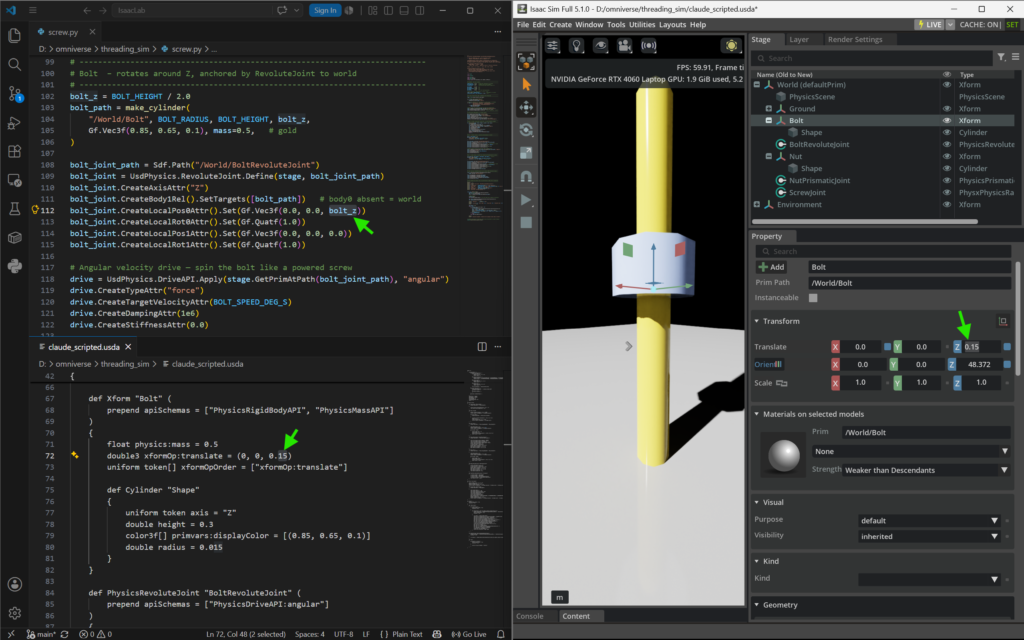
This is an excellent way to learn how Python can be used to generate USD scenes, while also understanding how USD feeds Omniverse user interfaces. That’s exactly how I improved my understanding of how this project needed to be setup, allowing me to create the same simulation using only the UI.
I used Devin AI to help me understand how to build the static bolt version, which I saved as a .usda file so I could study the data to understand the difference.
Setting up the mimic joint version was a bit more challenging to grasp in the Isaac Sim UI, but I kept practicing until I could replicate it consistently and understood how the parameters effect the simulation.
Building Our Digital Twins
Let’s walk through the steps of how to set up both of our simulations.
CAD-to-USD
Before we jump into Isaac Sim, we’ll start by exporting the CAD files from OnShape in the JT format, which we’ll use to convert the separate parts into USD. I’ve already done that and provided those files in the hex_bolt folder of the project repo to make this easier for you.
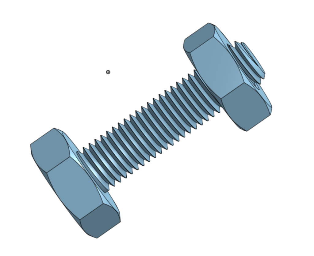
I ran into issues converting the JT files to USD using Isaac Sim, so I spun up Omniverse USD Composer to handle this process. You can see how I did this in the video walkthrough.
Isaac Sim Project Set Up: Rotating Bolt (Rack-and-Pinion Joint)
Start Isaac Sim with an empty scene and set the lights to Default.

Create a ground plane by going to Create > Physics > Ground Plane.
Add a physics scene by going to Create > Physics > Physics Scene.
Adding Parts with Physics
Go to the Stage tab and right-click to create a new Xform and rename that to “Bolt”. Now, you can right-click that Bolt Xform and add a Reference to the Bolt.usd in the hex_bolt folder. With the Bolt selected, you can hit the “F” key to bring it into focus in the preview window.
Next, you can follow that same process to create an Xform for the Nut, and add a reference to the Nut.usd file. Drag the Nut up so it’s just above the bolt hex.
We need to add physics to both our Nut and Bolt, so right-click each one and apply Add > Physics > Rigid Body with Collision Preset, so they can be moved by the joints that we’ll add next.
Adding Joints
Now that we have our parts in place, we can add our joints.
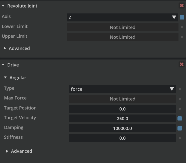
Right-click the Bolt and go to Create > Physics > Joint > Revolute Joint, which will add the rotation joint we’ll use to spin the bolt. Go to the properties and change the axis to Z.
Scroll back up to the top of the properties and click the + button to add Physics > Angular Drive to allow our bolt to rotate. Here’s a screenshot of our bolt’s revolute joint settings:
Follow the previous steps and add a Prismatic Joint to the Nut with these settings:
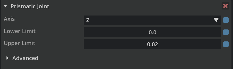
The prismatic joint does not need a drive added in this case.
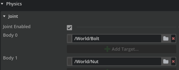
Next, right-click World in the stage tab and create a Rack and Pinion joint, which also does not need a drive. Adjust the Body0 parameter to point to our Bolt and Body1 value to point to the Nut, as shown below:
The last step is to add the appropriate Hinge and Prismatic targets, along with the proper Ratio value, to our Rack and Pinion joint:
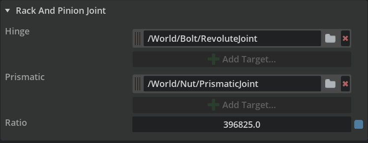
The Ratio value will vary based on your specific project, since it’s what determines how fast the nut moves compared to the spin of the drive.
If you haven’t already, be sure to save your project!
Run The Simulation
Now, you can hit the play button to run the simulation and watch the bolt spin as the nut moves up to the top. If you wait for the simulation to play out, you’ll find the nut stops at the top, which is due to the the Target Velocity parameter we added to our revolute joint. If you adjust that value to 900, you’ll find the Nut keeps going beyond the height of the bolt.
Isaac Sim Project Set Up: Static Bolt (Mimic Joint)
Start Isaac Sim with an empty scene and set the lights to Default.
Create a ground plane by going to Create > Physics > Ground Plane.
Add a physics scene by going to Create > Physics > Physics Scene.
Adding Parts with Physics
Go to the Stage tab and right-click to create an XForm and call it NutAssembly. Nesting our nut and bolt under this is a key difference in this build!
Right-click the NutAssembly and apply Add > Physics > Articulation Root, making sure to uncheck the Self Collision Enabled box in the parameters.
Now you can right-click the NutAssembly to create a new child Xform and rename that to “Bolt”. Right-click that Bolt Xform and add a Reference to the Bolt.usd in the hex_bolt folder. With the Bolt selected, you can hit the “F” key to bring it into focus in the preview window.
Next, you can follow that same process to create another NutAssembly child Xform for the Nut, and add a reference to the Nut.usd file. Drag the Nut up so it’s just above the bolt hex, which should be 0.005 on the Z axis.
Troubleshooting Tip: If you find the nut isn’t visible unless it’s Z axis is set to 5.0, then your CAD imports didn’t reduce the scale automatically. You can resolve this by manually adjusting their scale to 0.001, which is important for the settings provided below to work.
Add one more child Xform, which we’ll call NutSlide. This is what the nut will follow. You’ll want to set the Z Translate value on this to 0.005, as well.
Now, add a cube shape child to this Xform. You will need to reduce the scale down to 0.001 for it to match the rest of our CAD imported prims. If your scene goes dark, its because you’re inside the cube.
Add physics to all of the child Xforms, so right-click each one and apply Add > Physics > Rigid Body with Collision Preset, so they can be moved by the joints that we’ll add next. We also need to ensure the NutSlide has mass, so right-click that again and apply Add > Physics > Mass and be sure to set the Mass parameter to 0.1 so it has some weight. as it slides
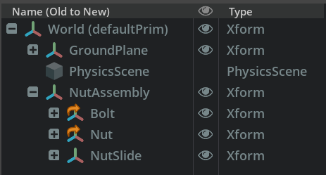
Now that we have our parts in place, we can add our joints.
Right-click the Bolt and go to Create > Physics > Joint > Fixed Joint, which will make sure our bolt does not rotate.
Right-click the Nut and go to Create > Physics > Joint > Revolute Joint, which will allow our nut to rotate. In the properties, set the axis to Z. Also, set the Lower Limit to -100000 and the Upper Limit to 100000. These are required for our mimic joint to work, which we’ll create soon.
Right-click the NutSlide and go to Create > Physics > Joint > Prismatic Joint, which is what our nut’s revolute joint will follow.
The Local Position 0 Z parameter should be 0.005, so it’s aligned with the nut’s position. If the nut jumps, double check this value.
Next, we need to set this prismatic joint’s Body 0 to /World/NutAssembly/Bolt which creates a relationship between these two prims.
Update the Axis to Z and set the Lower Limit to 0.005 with an Upper Limit of 0.025, which ensures out nut stops at the top of our bolt.
Now, we add a linear drive to the prismatic joint so our slide moves along the bolt. Right-click the joint and Add > Physics > Linear Drive.
Under the drive’s parameters, set the Target Velocity to 0.001 and the Damping to 10000.
The last piece of this puzzle is to go back to our nut’s revolute joint properties and set Body 0 to /World/NutAssembly/NutSlide.
Then, we right-click the joint again to Add >Physics > Mimic Joint. Set the Reference Joint to our Prismatic Joint and set Gearing to -240000.0, which is used to balance how fast our nut spins in relation to how far it moves.
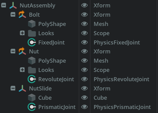
If you haven’t already, be sure to save your project!
Run The Simulation
Now, you can hit the play button to run the simulation and watch the nut spin up to the top as the bolt remains static. Change the linear drive value of the Prismatic Joint to -0.001 to see the nut move back down.
Customizing Settings For Your Project
You can adjust any of this to meet your specific project’s needs. If you have motor specs that you can replicate, or if you have the ability to do the math to define the appropriate ratio to match the drive rotation and linear speed you’re looking to replicate in your digital twin, then you’ll be in great shape. I tried to match the thread pitch in this case, but still don’t feel like I got it dialed in to match the real-world. Try adjusting the velocity and gear parameters to see what you think.
Conclusion
I personally found this seemingly simple simulation helped strengthen my skills in NVIDIA Isaac Sim enough that I had to share what I learned in case anyone else would find it useful. The Rack-and-Pinion Joint approach was a good starting point. I was a bit shocked that the static bolt version would be so much different, but I’m glad it gave me the opportunity to learn about setting up an articulation and that there was a Mimic Joint available to work with, which isn’t in the joint examples.
I highly recommend joining the NVIDIA Omniverse community to see what you can learn there and to ask for help on projects you get stuck on. If you’re already a pro, you can help others who might be stuck!
If you’re interested in learning more about joints in Isaac Sim, check out this video I made where I reverse engineer some examples, which was a helpful foundation for this specific project!